Background
This document provides a basic overview of building an HPC cluster. To help frame the discussion and provide a bit of context, let's suppose you've just secured the funds to purchase a Linux based HPC cluster and the physical components are sitting on your data center floor. Researchers are now eager to run their computations and your job is to get the cluster up and running. The following sections will describe a basic architecture for building out a cluster, the various technologies involved, and how Grendel can be leveraged to streamline the process. We'll show some simple uses cases for deploying Grendel and describe the services it provides. This introduction does not attempt to be a comprehensive guide to installing an HPC cluster and basic knowledge of HPC, Linux, and networking is assumed.
Basic Network Architecture
There are many architectures for building a HPC cluster and for the purposes of this introduction we'll be using a "Top-of-rack (ToR) switching" network architecture design. In this type of design compute nodes, switches, PDU's, and other components are located within the same (or adjacent rack) and are connected to an in-rack network switch commonly located at the top/middle of the rack. The in-rack network switch is then connected to a core aggregation switch or switches that connect the rest of the data center. After all the physical components are racked, cabled and powered on the individual compute nodes need an operating system installed and configured. To achieve this we'll need some basic information about each compute node such as:
- Host naming convention to assign hostnames
- IP Addressing scheme to assign an IP address to each node
- MAC Address of the networking interface
Host Naming Scheme
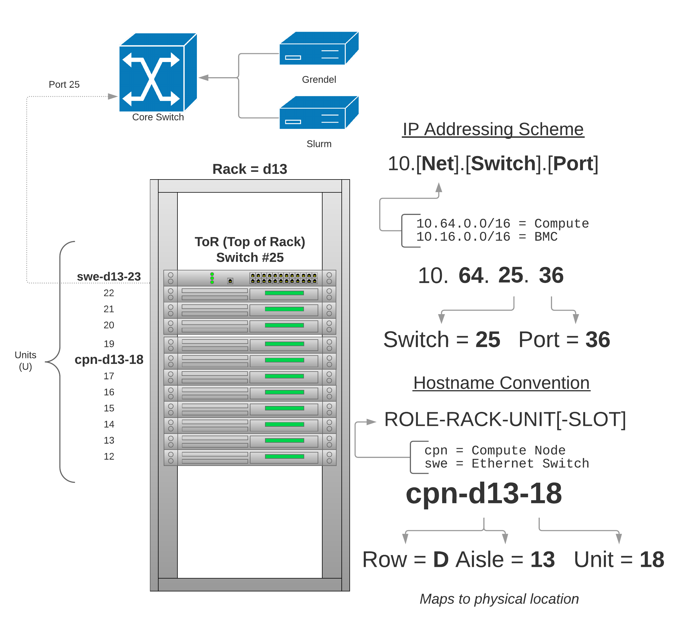
The host name scheme uses the compute nodes physical location within the data center to better help the system administrators service the nodes. The host naming convention is as follows:
Hostname Convention
ROLE-RACK-UNIT[-SLOT]
Each component (server, switch, PDU, etc) is named according to their role:
- cpn - compute node
- swe - ethernet switch
- swi - Infiniband switch
- pdu - Power distribution unit
Followed by the physical rack in which they are located. Rack's are named based
on their location (row/aisle) in the data center. For example, rack d13 is
located in row D aisle 13. The last component of the name is the unit
within the rack followed by an optional "slot". The slot is for compute node
chassis that have more than one node within the same rack unit. For example,
the dell C6420's are 2U servers with 4 compute nodes (2 in each rack unit).
These compute nodes would get names like:
- cpn-d13-18-02
- cpn-d13-18-01
- cpn-d13-19-01
- cpn-d13-19-02
IP Addressing Scheme
To assign IP addresses to each compute node the following scheme is used:
IP Addressing Scheme
10.[Net].[Switch].[Port]
Class B subnets are created for each high level grouping of services. As a simple example, suppose the following 3 networks:
10.64.0.0/16- HPC compute nodes10.16.0.0/16- BMC management network10.32.0.0/16- Core services
All compute servers will live on 10.64.0.0/16, a management network
10.16.0.0/16 is created for the BMC devices for out of band management of the
nodes, and 10.32.0.0/16 will be used for core services like DHCP, DNS, LDAP,
etc.
Each ToR switch will have a number, this could be for example based on the port
it's plugged into on the core switch. For example, the ToR switch in rack d13
is plugged into port 25 on the core switch so we'll number this 25. Each
switch will have it's own VLANID and subnet for each network. Continuing with
our example, for the compute network switch number 25 will have VLANID 1025
and subnet 10.64.25.0/24. For the BMC network, switch number 25 will have
VLANDI 3025 and subnet 10.16.25.0/24 and so on.
Each node in rack d13 will be assigned an IP address based on the port it's
plugged into on the ToR switch. As a complete working example, the compute node
physically located in rack d13 unit 18 plugged into port 36 on ToR switch 25
would have IP address 10.64.25.36.
Overview
The diagram below shows a typical ToR architecture and the basic IP and host name addressing scheme described in the sections above:
Auto-Discovery of Hosts
Depending on how the BIOS are configured from the factory, after the compute nodes are powered on for the very first time they will typically attempt to a network boot via PXE. The ToR switches are typically configured to relay DHCP packets to one or more DHCP servers in the data center. Here we configure all ToR switches to relay DHCP requests to our Grendel server. Grendel can now be used to harvest the MAC addresses of each compute node using one of the host auto-discovery methods. After the hosts are loaded into Grendel they can be provisioned.
Discover hosts using switch
Assuming we're using the IP addressing scheme described in the previous section we can interrogate the ToR switch MAC address table to auto-discover hosts and load them into Grendel. This works by using either SNMP or the RedFish API on the switch to obtain the MAC address table listing out the MAC address, port number, and VLANID. We can then provide Grendel a simple text file of hostname to port mapping to automatically load hosts into Grendel.
$ grendel discover switch --endpoint swe-d13-25 --mapping hosts.txt --subnet 10.64.0.0
Discover hosts using DHCP
If we're not concerned with mapping host names to physical locations or don't have a particular IP addressing scheme we can use DHCP to auto-discover hosts and load them into Grendel. Here we assume we have a rack of hosts continuously sending out DHCP boot requests. The goal here is to capture the MAC addresses of the requests and assign them a hostname and IP address in a contiguous manner. We can run Grendel with the following command providing a subnet and a nodeset for assigning host names:
$ grendel discover dhcp --subnet 10.64.0.0 --nodeset tux-[01-100]
Discover hosts using a file
If you have an existing DHCP server you can load hosts into Grendel using a
dhcpd.leases file. Grendel also supports loading hosts via a simple tab
delimited text file. You can use this method if you have obtained the host
names, IP, and MAC addresses via other means and simply want to load these into
Grendel.
$ grendel discover file --input hosts.txt
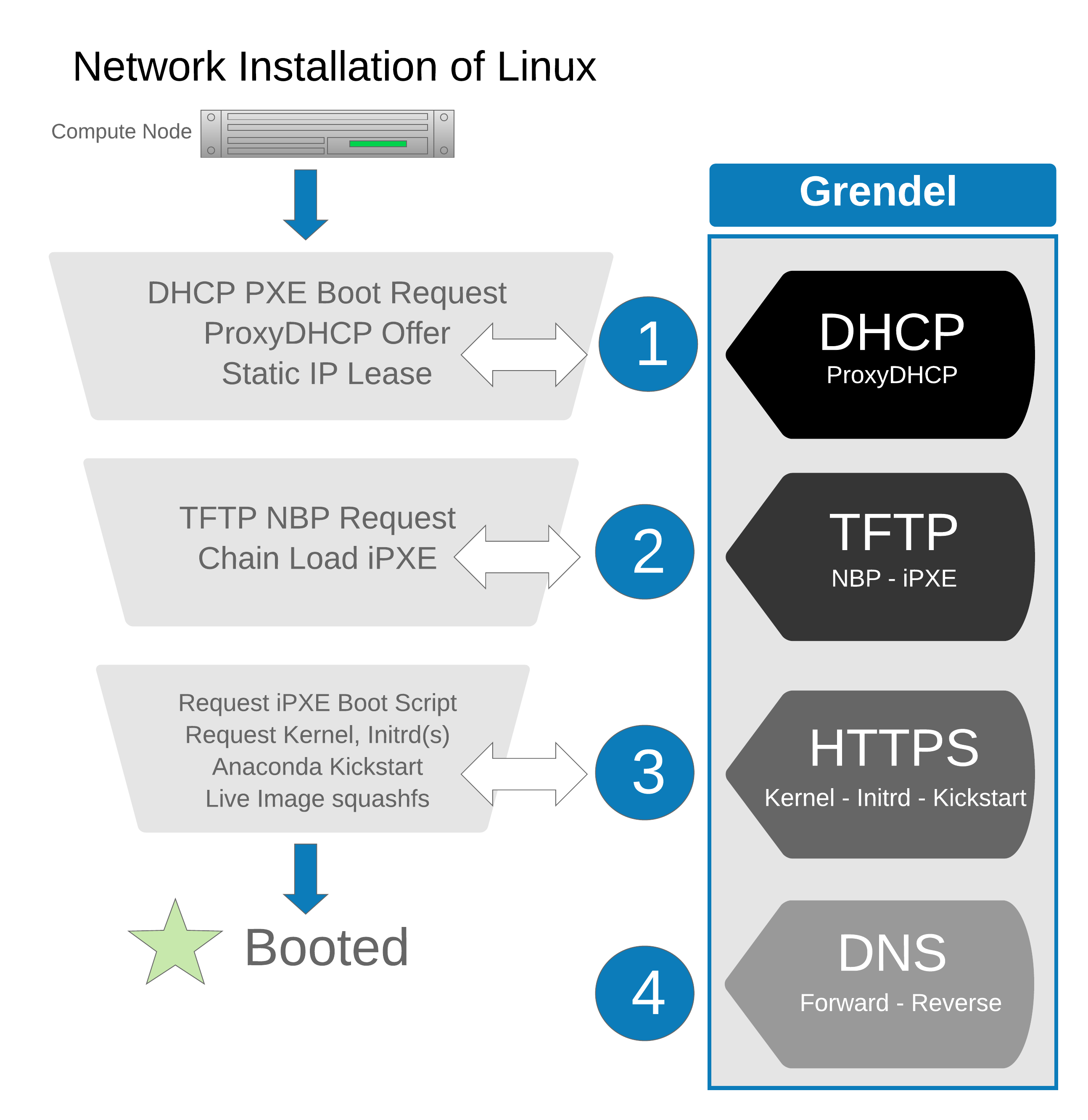
Boot process overview
Grendel provides an implementation of network protocols required to provision Linux systems over a network in a single binary:
- DHCP - Static leases and ProxyDHP (PXE) server
- TFTP - Used to chain load iPXE open source network boot firmware
- HTTPS - Serve iPXE boot scripts, kernel/initrd, Kickstart and Live images
- DNS - Forward and reverse name resolution for compute nodes
Grendel also provides a CLI and rest API for managing hosts and OS images. A high-level overview of installing Linux over the network using Grendel is shown below:
Grendel can be deployed in several different ways depending on your level of commitment. You can enable/disable any combination of the above network services depending on your existing setup. For example, if you already have an existing DHCP server, Grendel can run a ProxyDHCP server only and will serve PXE boot requests but not provide any static leases. Used in combination with the HTTP server, Grendel can serve up the provision assets such as iPXE boot script, kernels, initrds, and anaconda kickstart files.